The Rest of the Keyboard
This is going to be somewhat reminscent of that owl meme. I had plans for some more posts about a new codec abstraction, my async STM32 IO crate, and maybe the overall architecture, but one thing led to another, and now I have a complete project to talk about. I'll give an overview of the main points of interest so that the other rust/embedded posts aren't required reading. I'm also kind of writing to two audiences here, so if you're a Rust person, but not a keeb person, feel free to skip stuff and vice-versa.
The Polymer Keyboard
Overview
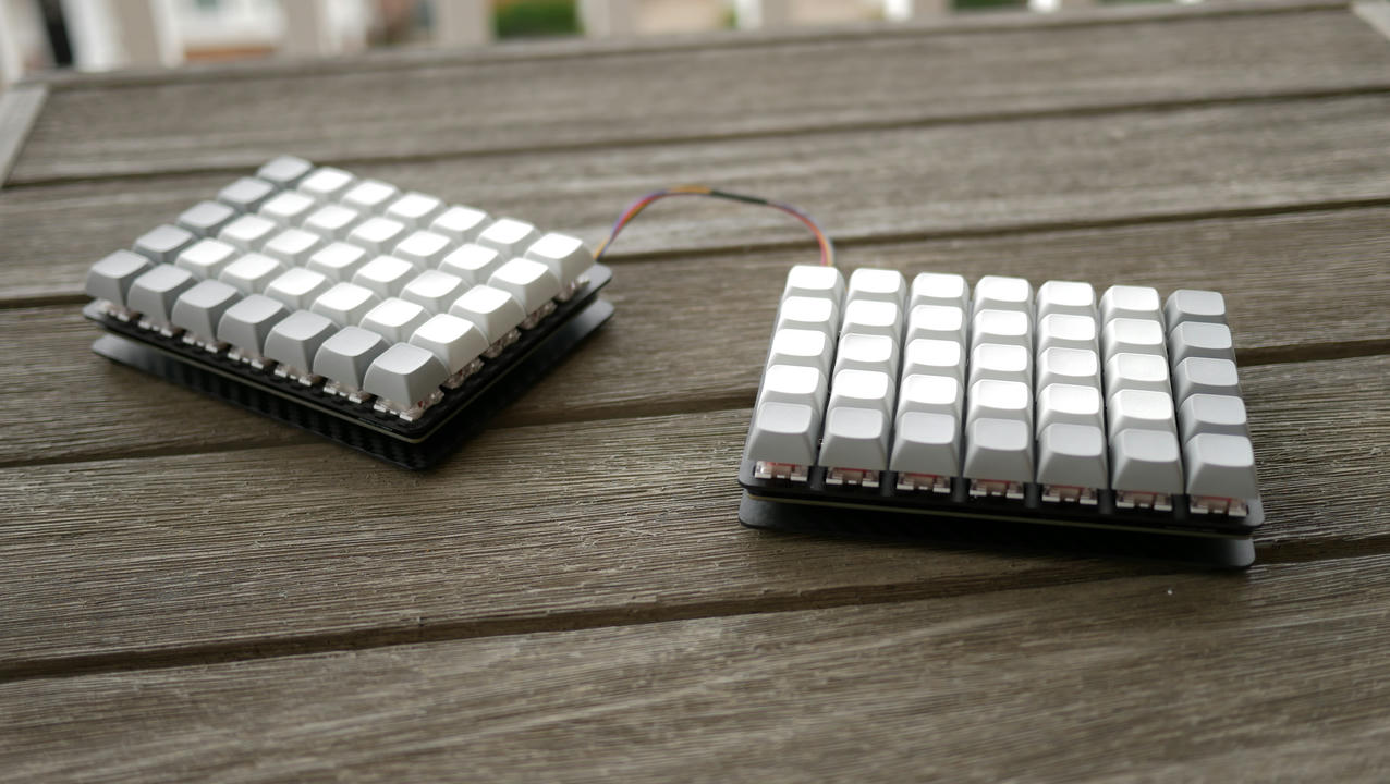
Ok, so while there are probably some polymer materials somewhere in the keyboard's construction, the name has nothing to do with its composition. Instead, it refers to one of its more interesting features: chainability. As far as I know, most split-keyboard designs, such as the Let's Split or ErgoDox have been limited to two boards/modules. The Polymer, by contrast, supports up to 255 modules via daisy-chaining. Its firmware is built with Rust and runs on stm32f103 BluePill-like microcontrollers. It supports NKRO, macros, and some media/extra keys.

The Chain
Each module has two serial ports, a left and a right, by which it connects to its neighbors. They all scan their respective matrices independently and only transmit changes along the chain to the primary module to which the USB cable is attached. The overall layout of the board can be duplicated in the firmware of each module, so changing the primary board doesn't require any reconfiguration. In order to account for differently shaped modules, the layout is defined by a list of "typed" modules, and modules announce their type on startup. This way, you never run into a situation where a module sends a key update that's "off the edge" of the layout. It also means that the board is somewhat resilient to changes in its composition without requiring reconfiguration, since missing modules in the chain can be ignored.
This is accomplished by mapping each module's physical position in the chain to a logical position in the layout. Logically, from left to right, the modules are numbered starting from 0. Physically, however, their numbering is based on the USB cable, with the left modules having negative numbers, the right modules positive, and the USB-connected module at the "center" 0. The primary module attempts to match the physical position/type pairs that it receives from the other modules on startup to their logical position in the actual layout. It will preserve the left-to-right ordering of modules with the same type, but is otherwise flexible. So if you had a small module for macro purposes, you should be able to change its physical position in the chain and have it get correctly matched up with the logical layout.
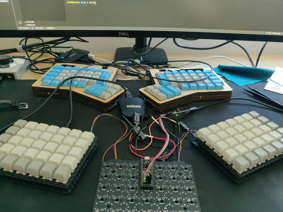
Another fun aspect of this design is that I was able to build a "debug" module with no keys of its own that I can insert into any part of the chain to do things like snoop on messages from other modules, hook up my BMP, or get easy access to the microcontroller pins with a logic analyzer.
Here's a pic of the debug module stuck between my two main ones. I've got a logic analyzer hooked up to analyze the serial messages flying back and forth, and a bmp attached to its SWD pins. Apologies for the messy desk.

Macros
Each position in the keymap is represented by an enumeration of possible actions:
There are a few more variants, but we'll get to those later. Single keys and
multiple keys are fairly straightforward and behave as you would expect.
Sequences are a bit more interesting. Because its definition is recursive, a
Seq can be made up of a series of single keys, key combinations, or even
nested sequences! This means that macros can get quite complex. For example:
// Note: This is for linux IBus. YMMV on other systems.
const START_UNICODE: Action = Combo;
const SHRUG_HAND: Action = Seq;
const SHRUG_FACE: Action = unicode!;
const USCORE: Action = Combo;
const LPAREN: Action = Combo;
const RPAREN: Action = Combo;
const SHRUGGIE: Action = Seq;
Layers
Layers operate similarly to how they work in QMK. Each layer has a static
position relative to the others and can be turned on or off using some more
variants of the Action enum:
A Layer action toggles the specified layer. A Trans action "falls
through" to a lower layer. Because it is sometimes desirable to have layers
behave like modifiers rather than "locked" overlays, a Trans action on the
destination layer in the same position as the Layer action that triggered
it causes that layer to be disabled when the key is released.
Hardware
PCB
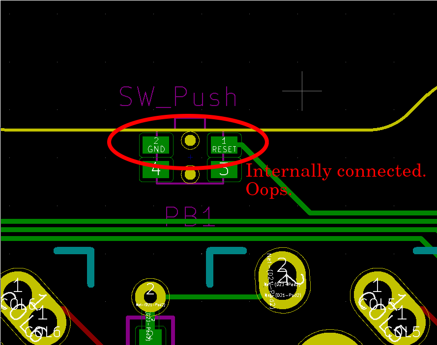
I designed the PCB in KiCAD. It's fairly bare-bones and has been through a couple of iterations. In the first version, I had a few pins mapped to rows/columns that I would have preferred to stay open, like the JTAG pins and one shared by the LED. Remedying this required quite a bit of re-routing and a firmware update. My second version also added a reset button and was almost perfect, aside from one small flaw. The footprint I used for the reset button didn't have the pins mapped to the schematic as I expected, which caused me to wire GND and RESET to two pins on the switch that were internally connected. Whoops. I only discovered this when assembling my final boards, so I had to cut a trace and run a jumper. Not the end of the world, but it does mean that the final(ish) version differs ever so slightly from the one I'm using day-to-day. I've been having my PCBs fabricated by JLCPCB and haven't ad an issue with them yet.

Case
For the case, I went with a simple two-plate design. I drew it up in LibreCAD and had it cut from carbon fiber from Armattan, a company that makes quadcopter frames that I've used before. Everything here worked pretty much exactly as planned. They also let you set up a little store so other people can purchase your designs. Switches fit a little snugly, but aren't too hard to snap into place. When the microcontroller is installed using Peel-A-Way sockets, I managed to get it assembled using 12mm standoffs.
Connectors
For whatever reason, the standard way to connect split keyboards has been via TRRS cables. These have the downside of not being hot-pluggable because of all of the shorting that can occur while the cable is partially-plugged. I instead opted for the JST connectors used by SparkFun's qwiic ecosystem. These have the advantage of being more hot-plug friendly since the pins only make contact with their other half when being plugged in, and can't be plugged in the wrong way. The only downside is that I'm running 5v over it, while the qwiic ecosystem uses 3v. So not only will your qwiic peripheral not work when plugged into your keyboard due to the I2C vs USART problem, it's also likely to get fried. I don't plan on attempting that though, so it's a non-issue for me.
Rust Impelementation Details
Generic Core
I tried to keep the bulk of the code in an abstract "core" library, keebrs.
It uses existing traits to be generic over the actual IO methods that may be
used on real hardware, so it should theoretically be fairly straightforward
to port to a new architecture. For example, the scan timer is represented by
an async Stream, keystrokes are sent to the USB device via a Sink, and the
serial ports are represented by embrio's async Read and Write objects.
In addition to improved portability, this also means that much of the
codebase is testable via mocked IO objects like in-memory buffers, and bugs
can be caught and fixed without needing to fight with actual hardware.
Async/Await
My goal from the beginning was to make the firmware as async/await as possible. Because the design could potentially involve a lot of messages passing between modules, it's important for the IO to be handled promptly, but also for it to not get in the way of other tasks like matrix scanning. This could have been accomplished by using interrupts and a "main loop" that juggles the various tasks, but that felt like it was going to end up looking pretty similar to Rust's reactor/executor async/await model anyway, so why not go for it?
Initially, that required the use of embrio-async to desugar to generators
and to emulate resume args since the usual desugaring required thread-local
storage, which doesn't exist on embedded devices. Recently, however, resume
args have made their way into Rust nightly, so the async/await transform now
works out of the box! Nightly is stll required for async/await on no_std,
plus a couple of other features, but we're quickly approaching a point where
my firmware will build with stable Rust.
Mini-Reactors
In the Rust async world, the "executor" is responsible for making sure that tasks requiring IO get executed when the IO is available. But what actually monitors the low-level IO devices for readiness and "wakes up" the task in the executor? In runtimes backed by a full OS, there's usually a "reactor" that's backed by some kernel-provided IO event system that's responsible for receiving readiness events and triggering the wakeups. This can either live in a dedicated thread, or as a part of the executor. In embedded systems without an OS or threads, one option for generating these wakeups is via interrupts.
In my stm32f1xx-futures crate, each async IO object is backed by a miniature "reactor" that needs to be "turned" by its respective interrupt. Turning the reactor usually involves checking peripheral flags, and copying new bytes to or from buffers, and then notifying the tasks that have registered interest if needed. This 1:1 relationship between the async IO object and its reactor ensures that you only need to bring in the bare minimum to drive the IO that you need, rather than a "kitchen sink" reactor that you may not need most of.
Note: the following example code ignores the problem of sharing variables
among init, idle, and the USART1 interrupt.
// Interrupt vector
Right now, my crate only supports minimal timers and non-DMA serial ports
since those were all I needed. Eventually, it would be awesome to support
more peripherals, but I suspect that they will need some extra traits beyond
Read/Write/Stream.
Message Serialization
Serialization has been a pretty well-solved problem for the majority of
Rust's life via the serde family of crates. As it turns out, they work just
as well for no_std! Postcard provides an excellend serde backend for
embedded devices, and even provides built-in support for COBS for easy
packet framing.
The only thing missing was an easy way to layer the serialization method on
top of a read/write object to create a Stream/Sink for structured
messages. Unfortunately, the de-facto standard for this is tokio's
codec module, which isn't no_std friendly, and forces the use
of the BytesMut struct. So of course, I wrote my own abstraction
that supports no_std and simple byte slices rather than the types from
bytes.
What's Next?
What isn't next? QMK, the metric by which all other keyboard firmwares will inevitably be measured by, has a huge list of features (not exhaustive by a long shot).
One thing that's obviously lacking is any support for lighting. It's not something that I particularly feel the need for, but it seems like a lot of other people like it. TheZoq2 started preliminary work on it, but ran into some issues with the core architecture in keebrs that I promised I'd solve before falling off the wagon and letting the project stall for half a year.
Some other things I'd love to add are some quality-of-life improvements to layout definitions. IMO, they're not bad as-is, but some compile-time machinery to generate actions from text for things like macros, unicode literals, etc. would be nice to have. I'd much rather see "¯\_(ツ)_/¯" in a layout than the raw key sequence.
There's also a need for a lot more documentation. Most of keebrs is
pretty well commented, and I've got some blog posts about the executor, but
there's nothing meant for people who are interested in building it or
designing their own modules. I'm hoping if it ever reaches that level of
interest, some kind soul might help out with that 😁.